
 Wagon Makers
![Conestoga Wagon - Figure 8.—Freight-Carrying Wagon of the Period 1800-1820. (Drawing by Donald W. Holst.)]](/Society/SotT/Conestoga/wagonparts11.jpg)
Figure 8.—Freight-Carrying Wagon of the Period 1800-1820. (Drawing by Donald W. Holst.)]
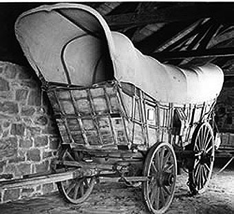
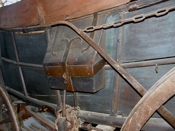
a: Bed and running gear, right side: 1, Bows for supporting cover. 2, Ridgepole, or stringer. 3, Top rail, with bow staples and side-board staples. 4, Side-boards, removable. 5, Feedbox in traveling position. 6, Rubbing plates to prevent wheels wearing wooden frame. 7, Side-board standards, forming framework of sides (on the inside, a few of these sometimes project a few inches above the top rail to support the side-boards). 9, Securing rings for the ends of the spread chains, two of which span the bed to give extra support to the sides against inside pressures.
b: Tongue, or pole, top and side views: 1, doubletree hasp, shown in proper position over the doubletree in the lower drawing: the hammer-headed doubletree pin goes through it, then through the doubletree and the tongue. 2, Wear plate for doubletree pin. 3, Feedbox staple; in use, the feedbox is unhooked from the rear, the long pin on one end of the box is passed through the hole for the doubletree pin, and the lug on the other end of the box is slipped through the staple. 4, Hitching rings, for securing horses while feeding. 5, End ring.
![Conestoga Wagon - [Figure 9.—Details of the Freight-Carrying Wagon, 1800-1820, of Figure 8. (Drawing by Donald W. Holst.)]](/Society/SotT/Conestoga/wagonparts21.jpg)
[Figure 9.—Details of the Freight-Carrying Wagon, 1800-1820, of Figure 8. (Drawing by Donald W. Holst.)]
b: Brake mechanism, detail: 1, Brake rocker bar, with squared end for brake lever. 2, Rods connecting rocker bar to brake beam. 3, Rubber, or brakeshoe, made of wood, often faced with old leather. 4, Brake beam. 5, Brake-beam shelf, or support. 6, Brake lever, often 4 or 5 feet long.
c: Front axletree and bolsters, front view: 1, Axletree. 2, Bolster, showing wear plates. 3, Upper bolster, actually part of the wagon bed. 4, Axle, showing ironing.
d: Rear axletree and bolster, rear view: 1, Axle tree, showing linchpin in position in right axle. 2, Bolster. 3, Hook and staple for holding bucket of tar used in lubricating axles. 4, Hound pins.
e: Toolbox, showing front, end, and top; it was secured to left side of wagon.
f: Doubletree, with singletrees attached.
g: Brake mechanism, side view.

Figure 10.—Details of the Freight-Carrying Wagon, 1800-1820, of Figure 8. (Drawing by Donald W. Holst.)
b: Front end panel: 1, Bottom end rail. 2, Middle end rail. 3, Top end rail. 4, Standard, or upright, forming end framing. 5, End boards. 6, Bow. 7, Corner plates.
c: Rear end gate: 1, Staples for end-gate standards. 2, End-gate hasps and hooks. 3, Pins to secure gate to upper side rails. 4, Crossbar to give extra support to end gate.
d: Rear wheel.
e: Cross section of wheel: 1, Boxings, of cast iron, wedged in hub to take wear of axle.
f: Front wheel: 1, Felly, or felloe. 2, Spoke. 3, Hub, or nave.
g: Floor of wagon, from under side: 1, Crossbeams, the center and rear ones being heavier, and projecting at the ends to hold the iron side braces visible in figure 8,a. 2, Bottom side rails. 3, Floorboards. 4, Position of rear bolster when bed is on running gear. 5, Front bolster, showing hole for kingpin.
Source: Research and Text by Bryan Wright


